1949 MG TC Resto- mod.

This picture of the radiator grille and surround gives a clue to the standard of build that I am hoping to achieve. I found to my surprise that the original radiator was in very good condition. I have to say I was impressed with it's construction which is entirely from brass and copper. I think it could be fairly described as a work of art. The grille, however required a lot of fettling and chrome plating which I handed over to Derby Platers. They are excellent but expensive. The emblem was damaged and being black and white was for a later car anyway. I was incredibly fortunate in finding a perfect 1949 MG emblem.
img_0806-2-jpg.8901
 
Last edited by a moderator:
One of the mods that really gets the purists foaming at the mouth is if someone dares to change the windscreen wiper layout. Originally, a Lucas 12 volt wiper motor was bolted to the top of the screen frame. This then drove a passenger side wiper arm with a rod that linked across the screen to an idler wiper on the driver side. There was no form of remote control as the switch was located on the motor itself. There was also no self park facility. the driver had to reach up to it to switch on and then judge when to switch off. Nightmare!

I personally find it annoying to have an ugly back lump in my eye line. It is also inherently dangerous particularly for a passenger who risks having their head impaled in a collision, especially as only a lap belt is likely to be fitted; assuming any are fitted at all.

I am tempted to make a change to a more modern wiper motor fitted under the dash with the wipers located through the scuttle in the conventional way. This would give me one or two speeds and a park facility. I could also include an electric screen wash.

It has to be admitted, however, that the traditional appearance would be altered with the screen appearing less cluttered. A possible downside is that the folding screen is compromised. I would need to remove the wiper blades to allow the screen to fold flat. As I have no intention of driving with the screen down the issue seems irrelevant.

What I need to decide is the exact type of motor etc. The options are mind boggling and the costs variable.
 
Last edited:
One reason why any resto-mod takes longer than a standard equivalent is that so many choices and decisions have to be made that stray from the original design. In this case it is the windscreen wipers. I have now changed direction again and decided to retain the original wiper motor. (A modification to 'under scuttle' operation can wait until the car is roadworthy.) This is a Lucas CWX motor and is in reasonable condition but needed some TLC. I had to re - insulate the two wires from the terminal block with heat shrink and the two part switch needed replacement as half of it was missing. Fortunately, new ones are available. The grease in the gearbox had hardened so I replaced it with the recommended PH white.

I have sanded the case in readiness for black wrinkle finish paint .


The wires feeding the wiper motor are rather inconveniently trapped behind the glass in it's chrome plated brass frame (Two holes are provided for the purpose). There is also a grommeted hole in the scuttle. The original `'duplex" type flex is no longer available but I have sourced a suitable replacement. Fortunately, I have yet to fit the glass so I can correctly route the wires to the motor.

As I say, this area of modification will have to wait...
 
Last edited:
Sometimes there are things that happen which simply shouldn't. The folding windscreen on these old cars is screwed through the scuttle into the supporting timber frame. What shouldn't get in the way is a steel strengthening bracket. In this case it came directly in line with the pillar screws. I had to drill 4mm holes then tap 2 BA threads in two of the brackets. It is difficult to line everything up but I got there eventually.

The windscreen is now (temporarily) fitted but it was not as easy as it could have been because on repairing a corroded part of the scuttle I lost the screw holes so I needed to carefully measure one side then the other.


All good fun!
 
Last edited:


Here is a frustrating problem. Having bought a new rubber gearbox cover (replica of original) it is disappointing, to say the least, that it appears not to fit. The photo shows how the cover needs to wrap around the gearbox mounting but fails to do so. I may be able to stretch the cover by using my electric heat gun, but I will need to be careful not to cause irreparable damage.

The other issue is that I bought bespoke replacement plywood floors to save time in making them myself. Unfortunately, they also don't fit and have needed further work. Fortunately, I have the necessary woodworking tools to make the alterations.
 
In an earlier post I explained how I had modified the braking system with the addition of a remote brake fluid reservoir so that in future the fluid level could be checked without recourse to grovelling about on the floor to gain access.IMG-0475.jpg IMG-0477.jpg

A consequence of this is that the access hole in the 3/8" plywood floor board is now redundant.

I could have replaced the original metal cover but instead I decided to let in a plug made from 3mm plywood.
The photos show the rebated opening to accept a flush fitting disc. The main advantage is that it lays flush with the floor and is easily removable...but can't come out accidentally.

IMG_1319.JPGIMG_1320.JPG
 
I had a call from the Coach builders this morning. It will be remembered that they have my new rear wings which need fettling. They will need the car in their workshop to ensure they get it right. I have been told it will take two days work - or 16 hours labour.

So much for 'ready to fit' panels.!
 
Just to summarise the progress so far. The dashboard is now covered in leather and ready to be screwed to go on the car but I need to paint the (double humped) scuttle top first because masking off the dashboard where it meets the scuttle edge would be risky. Unfortunately, the dash is being delayed, because although I will be spraying in my garage, the humidity level needs to be at not much more than 50%... and of late the hygrometer has been showing readings of +70%.!

I have had a few issues fitting the new petrol tank to the back board of the body. The tank "feet" should sit flat on the chassis and the back of the tank should automatically lay against 1/4" thick rubber strips screwed to the upright back board of the body tub. Unfortunately, the tank must have been made slightly "out" because although it touches at the top it leaves an unsightly gap towards the bottom. The tank is held to the body by two metal straps (with strip rubber padding) that are screwed to the body at the top (hidden by the hood material) and at the bottom by ring clamps bolted to the tubular chassis cross member. In what I can only describe as a "dodge" I have made it fit the back board. The feet will not be seen, but they sit awkwardly on rubber pads on the chassis. Sometimes we just have to compromise.

Both floor sections are painted and fitted and I have temporarily fitted the front wings and running boards so the body shop will have something to work to.

It has been a struggle getting both sides the same!
 
Last edited:
When I got the MG it had no hood fitted, but fortunately the frame came with the car; along with a set of decrepit side screens. I wish I had taken some before and after photos of the frame because it was in a terrible condition. Someone had smothered thick black paint over rust. The frame was bent and had also been broken and welded...but badly ...and I have spent many hours restoring it. The difference is quite remarkable.

I found the best way to achieve a smooth finish was with an angle grinder; not with a grinding wheel but with a disc version of a flap wheel. More detailed work required judicious use of a variety of files and abrasive paper. I shall, of course, apply phosphorous acid to the steel before painting.


Here is a 'before' and 'after' shot of the hood/top front rail. The original Ash had perished beyond use so a new one was made by the supplier of the body tub.


I needed to tweak the metal frame to get it to fit, but once I had the rail clamped in place it was a simple matter of screwing them together.


The parts have now been separated again so that the frame can be treated with phosphoric acid prior to painting and the wooden rail has been given a coating of preservative paint.
 
As if I don't have enough on my plate, I have just discovered that the new dashboard that I have painstakingly covered in leather should have been made from 3/8" plywood but was in fact 1/2" thick. This means it won't fit properly in the car.

Short of making another dashboard the only thing I can do is thin down the 1" thick plywood backing board. Fortunately, this was easier than I imagined it would be but as you can see it made rather a mess!!

 
Another job connected with the dashboard is fitting the chrome beading to it's perimeter. Quite a few restorations have this original feature missing ...and at over £100 I can see why!!

The beading is chrome on brass and comes in two lengths; one that follows the double hump of the scuttle and the other that finishes the under side. I opted to countersink 13 holes for No.4 wood screws let into in the top section where they are hidden by piping...and used 7x No.4 chrome plated round head slotted wood screws for the underside where they can be seen.


I think it is worth while taking time to get the mitred corners as neat as possible.
 
Yet another problem (not of my making) is to do with fitting the hood tacking strips. The back of the body tub should be STRAIGHT (matching the top of the petrol tank) but it has been made with a slight curve. This means the piece of Ash to which the hood (fabric top) is attached does not align with the corner pieces.


I could plane the wood down but I think I will attempt to bend it if I can. It all takes time!
 
The MG was collected by I Wilkinson & Sons (Coach builders) this morning. It has been a frustrating three months wait for my car to be "fitted in" but now I am hopeful that things will move forward. I shall be visiting their premises next week to run through exactly what needs doing to the rear wings. They need the car there to ensure the "tweaked" wings fit properly.

 
I think it takes a particular type of individual who would see fit to paint a surface like this, but the previous owner had no qualms about covering it in shiny new paint. This is what I found when I removed the paint.


Here is the panel after some work to remove rust.


There was evidence of slight accident damage to the rounded front of the valance. I found an 'off cut' of heavy thick walled pipe matched exactly the curved profile and by placing the valance on the floor - protected by cardboard - I was able to use it as a bolster type dolly and knocked the panel back into shape.


The result was most satisfying.


A more localised dent required a smaller version

My next step is to saturate the panel in phosphoric acid then etch prime it prior to top coats of new paint.

I hope to have the valance ready to fit to the car when it returns from the coach works.
 
There is a truism that if you want a job doing properly then do it yourself.

The "professionals" obviously thought that this was "good enough".


Do I have "mug" stamped on my forehead?


.
 
These cars look older than they are. They have running boards... although to be fair they are only cosmetic. ( By means of a contrast, the ones on my 1926 Dodge Brothers tourer were substantial enough to stand on:lol:)
The running boards that were on my car when I got it had been mutilated beyond use so I answered an advertisement for a used pair of TC running boards in good condition. When they arrived it became clear that they were in fact TD panels that had been cut down to fit a TC. I could - or should - have returned them but after weighing up the pros and cons I decided to keep them.

The running boards each have two rubber treads fitted in aluminium supports. I bought new ones which meant a lot of measuring and drilling to allow for the 3/16" countersunk machine screws and securing nuts.

From the photo it can be seen that the TC had these treads tapering from front to back...where on the TD (from which they came) would have been parallel.


I am in the process of painting the rear wings and running boards. I have done the body tub so once these panels are finally fitted I should be able to get on with other things.
 
Filtering new paint is a wise precaution... but you don't expect to find this!


The supplier had no answer but agreed to send a new tin free of charge.

Fortunately, I have had no such issues with the replacement paint.


.
 
Last edited:
Is it just me?? I have just noticed a small pile of grit in the bottom of a tin of thinners.
I have tried using a pot filter but they only seem to work with thin paint. I am trying to spray high build primer.
I even found some bits in the primer.

I have had to thin the paint in one pot and filter it into another. That at least works. If the plonker who panelled the body and doors had made a better job of it I wouldn't have to spend so much time flatting down.
+++++++++++++++++++++++++++++++++++++++++++++++++++++++++++++++++++++++++++++++++
Unfortunately the petrol tank end panels that came with the car were too rusty to have chrome plated so I had to buy a new pair from Moss.

The new panels should be plated all over with just the edges polished. The flat faces should then be finished in body colour. These edges were shiny enough but the effect was inferior. 1) distorted reflection due to the way the panel had been stamped out. 2) A cheap chrome plating job which was not up to my standards.

I have left the end plates with Derby Plating. It should be 6 -8 weeks.
 
Last edited:
Filtering new paint is a wise precaution... but you don't expect to find this!


The supplier had no answer but agreed to send a new tin free of charge.

Fortunately, I have had no such issues with the replacement paint.


.
That’s awful and lucky could have wasted a lot of time in cleaning your tools and re preparing things !
 
Yes Jon. I must just be unlucky because I when I looked I also found a small pile of grit etc. in the bottom of a can of thinners that I had just finished. YES, THINNERS!! The worrying thing is that it came from a different supplier!

I know it is not my fault as I take great care to keep everything clean.

I have tried using a pot filter but it only works on thin paint. I have found that the fine mesh bags you get from the supermarket make ideal filtering material. I cut them up and tape a piece over the gun pot... mix paint and thinners in another pot, then filter it. Works for me.
 
My latest little set back has been resolved but I thought it would be worth sharing here. The stud has snapped off the left hand tank strap. Examination of the break revealed a long standing stress fracture; corrosion showed the fracture had started years ago so it was only a matter of time before it failed.


Maybe a bit primitive but I have made up a replacement stud and welded it to the tank strap.


Just paint required now.
 
A very clever guy in Germany called Declan Burns has a small business making and supplying MG parts. I have purchased a novel electronic fuel sender unit that works on the hydrostatic principle. The system has yet to be tested but I an hopeful because the quality of his products is the highest anywhere.

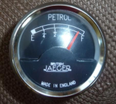
MG T-Series Fuel level gauge.
page1image53543120
This is a hydrostatic level sensor which connects into the fuel tank drain plug via a three way ball valve. The installation of the ball valve adds a user friendly drain facility. The arrangement at the bottom of the tank is shown in fig 1.
Fig 1. Installation arrangement
page1image53518048 page1image37374592
1) The sensor fig 2
The sensor is a hydrostatic fuel sensor-made in the EU. It has four buttons, a trim potentiometer and an LED for calibration. Connection to the dashboard via a Molex connector (supplied). Connection to the ball valve via a brass pressure port.
The function of the buttons is:
Set gauge min
Set gauge max
Set level empty
Set level full
page1image53531104
An initial calibration may be carried out with a 1 1⁄2 litre bottle of water on the bench. The details on this are given in the operating manual. Fuel density (DIN 228) is 720 to 775 kg/m3 or roughly 3⁄4 the density of water. Therefore 33cm water corresponds roughly to a full tank (43cm) of fuel.
2) The gauge
The sensor may be connected to a standard fuel gauge e.g.240 ... 33 Ohms empty to full.
(Also tested on a 10 ... 90 Ohms empty to full.). Originally, the T-Series was never fitted with a fuel gauge... it was time for a reincarnation!.

Fig 3.(Example)

I have had a 52mm gauge built by 'British Jaeger' owner John Marks which has a more period looking dial face. The scale is non linear in an attempt to compensate for the shape of the tank.

Fig 3
page1image53713824
3) Connection
The gauge and the sensor require a +12V ... 0V connection. This is not an issue on cars that have been converted to negative earth. On cars that have the original positive earth, it is easy enough to make an isolated floating negative earth supply via the switched ignition using automotive relays. The details are shown on the cable harness wiring diagram provided. The actual length of cable required depends on the preferred routing of the cable. Approx. 4m (12ft) of cable harness is sufficient. The harness can be covered with polyester cable braid for protection. The corresponding Molex plugs and pins are included in the kit and will require crimping with a pliers. The wiring cable is not provided but specified.
Installing this system as recommended does require carefully drilling a 52mm hole in the dashboard (which is not what every owner wants to do but with my re-designed dash I am relaxed about it.)

Installation issues
The drain plug is slightly lower than the gauze filter on the fuel line. it may be advisable to fit an inline filter between gauge and sensor-see Fig 5. This has been tested and should does not affect the hydrostatic pressure.
Make sure there is no air trapped in the fuel hose between the sensor and the ball valve. This will lead to false readings if not bled correctly. It is best to fill a little fuel in the tank then fill the hose and sensor with fuel in the vertical position, open the ball valve very slightly so fuel just drops out and into a bucket placed under the ball valve. Then quickly fit the hose to the ball valve. It is also recommended to keep the fuel hose as short as possible. It is also imperative to make sure that the fuel filler cap is sufficiently vented.

page2image53542912 page2image53550608

Fig 5 Installation with filter. The handle on the ball valve was removed on this installation.

page2image53542912 page2image53550608

+++++++++++++++++++++++++++++++++++++++++++++++++++++++++++++++++++++++++++++++++

I have also fitted a low oil pressure sender/warning kit :

Despite the provision of an oil pressure gauge, a sudden loss of oil pressure can easily go unnoticed and prove expensive.! Better safe than sorry, I am intending to fit a warning light and buzzer.

The kit consists of a brake pressure adapter which allows a 'T' piece to be fitted in the pressure gauge line and a pre wired relay module mounted in a plastic case that can be fitted behind the dashboard. The kit also includes the wiring from the pressure switch to the relay module and the wire for the power supply including 2A fuse and buzzer.

A warning light can be suppled but I have today ordered a red dash warning light from Octagon spares to match and compliment the existing warning lights.

According to Declan:mad:(edit)

"When the ignition is switched on the buzzer is off and receives an operation permissive once the engine has been started and the oil pressure exceeds 20 psi. The buzzer going off every time the ignition is switched on would prove annoying. A test switch is fitted to the circuit to enable the buzzer to be tested. This is how it the system works:

Ignition ON & engine OFF, (no oil pressure),

warning light is ON and buzzer is OFF.

Start engine. When the pressure reaches 20psi the warning light goes OFF, and Buzzer remains OFF.

With engine ON & pressure drops below 20 psi, the warning light and buzzer come ON.

The warning light and buzzer stay on until reset by switching off the ignition.

This circuit is not polarity sensitive and is designed for cars with positive or negative earth.

* Other pressure switches other than 20psi are available. When ordering remember to tell me the value of your hot idle oil pressure."


Attachments

  • 1696461806905.png
    1696461806905.png
    276 KB · Views: 0
Last edited:


My new patrol tank end panel are at last back from the chrome Platers. These new panels were not especially well finished as they arrived from Moss so I have - at considerable expense - had them re done by 'Derby Platers Ltd.'. They are now to concours standard but the story doesn't end there. Followers of my MG TC rebuild will perhaps remember I had a new stainless steel petrol tank made but it's fixings would not properly align with the newly made rear wings to which they attach. I had to get two brackets moved forwards by 5mm but of course this meant the holes in the petrol tank end panels were now in the wrong place. I shall have to make fresh holes in the new end panels and disguise the original holes before over painting.

Just to clarify: it is only the outer edges of the panels that are polished chrome; the flat surfaces are painted body colour but the plating process entails having the entire panel dipped.
 
Restoration of a petrol cap? Yes. These cars have a unique chrome plated non lockable petrol cap with a quick release mechanism. The condition of the cap was rather poor condition but with great care and patience I was able to remove the outer cover and entrust it to 'Derby Platers' who made a first rate job of it.

.


These petrol caps are available as a reproduction. I purchased one but the quality just wasn't there so I returned it.

Another problem is the cork seal. Originally, this was fitted to the cap itself which is not a robust design and would not last long. I chose to make and fit a cork seal to the filler neck which I think should work better.

I also fitted a new spring and re made the hinge and clip pins.

 
Last edited:
I have been reading your posts about your TC "restomod" rebuild with interest. I just bought a 1949 MG TC with an "outside the frame" extractor exhaust manifold, also with an Eaton M45 supercharger. I'd like to switch to something similar to your manifold so I can refit the bonnet sides. May I ask where you purchased it?
 
Hello there. I bought my extractor manifold from Peter Edney (MG engineers) here in the U.K. but he is no longer selling parts. Having bought the manifold, however, I found I could not fit it without modification. It fouled the steering and the clutch lever. I could also not fit the original starter motor and had to buy a smaller one. In the end, I had to get the pipes bent differently to get it to fit. I then found it would not match up with the supercharger manifold and had to spend a lot of time with an angle grinder to get the ports to align.

In all, it was one of the worst purchases I have made. The exhaust specialist advised me that it had been made up from lots of short bends.

I would recommend you consult an exhaust specialist and get them to make you a bespoke system. It would probably not cost any more than what mine cost over all.

Best of luck.
 
The back of the MG is now looking more like a TC. I have wired up the rear lights and added indicators to each side of the tank. This may be non standard practice but they are more visible than if located down low. I have used standard Lucas 1130 side lights - just mounted sideways - with orange bulbs. I could have opted for LEDs but I inherited many 12 v bulbs for my late father, so not wishing to look a gift horse in the mouth, I decided to use them.

Incidentally the wiring for the indicators is hidden neatly behind the petrol tank end panels.

The externally mounted electronic hydrostatic sender unit ( hidden from view) is now working in conjunction with the gauge. This device - which has a "black box" secreted under the dash - operates completely independently of the fuel line. It is fitted in place of the original drain plug but is equipped with a manually operated gate valve and drain plug and filter. These cars were originally only fitted with a low level warning light - which still operates - but the new gauge has been made to match the other "British Jaeger" instruments. All the instruments are fully refurbished or new and some of the ivory coloured switches are vanishingly rare, so I have protected them with relays.

As can be seen - I have a working ignition warning light. The oil pressure light also now works but is not shown. The steering wheel is a "Brooklands Blumels" replica and is simply magnificent. As my VW steering box conversion is slightly lower geared compared with the original "Bishop Cam" I have opted for a 15 1/2" rather than the original 17" wheel.
 
Last edited:
For those of you who are interested in electrical 'up grades' here is my (strictly amateur) schematic diagram of the relays that I have installed to protect the fragile and rare dashboard switches. Note: positive earth.

I have utilised what would have been the tool box for the heater and the relays. The bulkhead mounted box had rotted through so I had no qualms about using it for the relays and the heater. There are two banks of four relays in compact blocks. The electric fan thermostat has also found a convenient home.

In addition I have supplemented the car's original two fuses with extra ones mounted under the dash. The fuse boxes are contemporary Lucas items. All the new holes are grommeted.

The red wires are from the ignition side and the dark blue wires are from the ammeter side.
 
Last edited:
One thing that hasn't gone to plan is the SU petrol pump. I bought a kit and rebuilt it with new points and diaphragm. I even installed a varistor to protect the electronics from stray voltage spikes ... but at the point of attempting a start up, the pump decided to to pump.

It clicks away happily but there is no suction. I don't have the patience to strip it all down again; especially as I don't know what exactly I am looking for, so I contacted Burlen. They said the pump was not viable...so I bought a new one.


One of my first mods with this car was the ignition system. Out with the old contact breaker points and condenser and in with a brand new electronic distributor. These are quite expensive items so you can imagine my frustration when I found that it would not fit. In order to be more compatible with a supercharger, the correct for XPAG engine distributor was eschewed in favour of one that would normally be fitted to a Mk1 Mini Cooper. Unfortunately, there was a flange at the bottom of the body that needed to be removed.

I mounted the distributor in my lathe and selected lowest speed. I then pared off the flange. Result! The distributor now fits.
 
It's the small things that take the time. I managed to loose one of the bonnet side buffers so had to make a new one. A simple enough job but I had to make it from what I had available. I took two rubber blanking grommets; one with a slightly domed face to match the front and one with a flat face to match the rear part. I then carefully cut the backs from both and bonded them to the re made metal part. The edge was finished nicely with a thin bead of 'tiger seal' liquid rubber and left to set.

Here I have the new buffer plate next to an original one. Not a perfect copy but it will do me.

 
Last edited:
I tried starting the rebuilt engine for the first time in 5 years. Amazingly, it started right up.! Unfortunately, the timing must be out as it kept backfiring through the supercharger blow off valve. I am at this point out of my comfort zone because I had set the timing according to the instructions that came with the CSI electronic distributor... (I did check the carburettor needle and it is the correct one).

Of the 16 settings, it is recommended that No.1 is most suitable... but something is not quite right somewhere.

I am expecting help from the supercharger supplier who will be coming over on Monday. He and his son are experts so hopefully we will get the car running properly with a timing light.
 
Last edited:
MG guru Steve Baker and his son Luke came over to my place as promised. It didn't take too long for Steve to determine the problem and I am ashamed to say it was entirely my fault. Although I had set the timing according to the CSI instructions, I had somehow managed to set it on the wrong stroke. I am mystified because I can distinctly remember feeling compression on No.1 cylinder (finger over plug hole) and checking the rockers were both free...but obviously I had not been careful enough because the fact remains that I had stuffed it up.

I felt like a complete chump for getting the guys out for such a basic error. I have apologised but they must think I am a right numpty. :mad::mad::mad:
 

Please watch this on my YouTube channel & Subscribe.


Back
Top